- Lte Slot Symbol Meaning
- Lte Slot Symbol Image
- Lte Slot Symbol Png
- Lte Slot Symbols
- Lte Subframe Symbol
- Lte Symbols Per Slot
Understanding how LTE transmission powers are calculated in Planet
The total transmission power of an LTE eNodeB is represented by its PA Power. In each symbol, the total power is shared by several transmission signals and channels:
- Cell-Specific Reference Signal (CS-RS)
- Primary and Secondary Synchronization Signal (SCH)
- Physical Broadcast Channel (PBCH)
- Physical Downlink Control Channel (PDCCH)
- Physical H-ARQ Indicator Channel (PHICH)
- Physical Control Format Indicator Channel (PCFICH)
- Physical Downlink Shared Channel (PDSCH)
Lte Slot Symbol Meaning
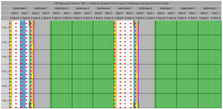
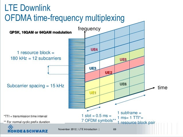
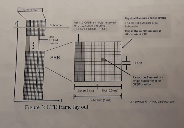
Symbols available in a slot. Then, 12 RE. 11 Symbols results in 132 RE available in a slot for NR PDSCH. In the case of one LTE CRS antenna port, the total available NR PDSCH REs available in a slot per one RB is 132-6 = 126 REs, 132-12 = 120 REs with two CRS antenna ports, and 132-16 = 116 REs with four CRS antenna ports.

Figure 40: LTE frame structure
- As Figure A.11 shows, the symbols are identical as regards cyclic prefixes in 4G LTE and 5G (n = 0). In fact, the only significant difference is the use of the term ‘slot’. You might recall that 4G LTE allows for an extended cyclic prefix with a length of 16.6 s for environments where the radio signal is subject to an unusually long delay.
- This model is used to demultiplex 3GPP LTE downlink slot. Each 10 ms radio frame consists of 20 slots of length, numbered from 0 to 19. Each 0.5 ms slot consists of 7 OFDM symbols for normal cyclic prefix or 6 OFDM symbols for extended cyclic prefix. The cyclic prefix of each OFDM symbol is removed in this model.
It is assumed that the PDCCH, PHICH, and PCFICH, all transmitted in the control region of the LTE subframe, all share the same transmit power. For simplification purposes, the term PDCCH is hence used to represent either the PDCCH, the PHICH, or the PCFICH.
For each symbol, how the total power is split across signals and channels depends on:
- How many resource elements (i.e. subcarriers) are used by the various signals and channels on that symbol
- How many resource elements (i.e. subcarriers) are left unused on that symbol
- Whether there is an energy boost applied to the cell-specific reference signal (CS-RS)
- Whether there is an energy boost applied to the synchronization signal (SCH) or the broadcast channel (PBCH)
- The power recycling strategy of the eNodeB, i.e. what the eNodeB does with the unused power of the resource elements with no allocated transmission on some or all transmission ports.
Cell-Specific Reference Signal (CS-RS)
Lte Slot Symbol Image
In LTE FDD and LTE TDD, the cell-specific reference signal is transmitted in the first and fifth symbols of each downlink slot. It occupies two of every 12 subcarriers in the single antenna case, and four of every 12 subcarriers if more transmit antennas are used. If there are at least four transmit antennas, the cell-specific reference signal is also transmitted in the second symbol of each downlink slot.
Figure 41: Illustration of transmit antenna configurations
Single antenna
When there is a single antenna, the reference signal is transmitted on the first and fifth symbols of each downlink slot, on two of every 12 subcarriers. Assuming no energy boost on the cell-specific reference signal, the total power used by CS-RS resource elements on each symbol is hence:

Two transmit antennas
When there are two transmit antennas, the reference signal is transmitted on the first and fifth symbols of each downlink slot, on four of every 12 subcarriers. It is important to note that if a resource element is used for the transmission of the CS-RS on one antenna port, it cannot be used on the second antenna port, as shown below.
Assuming there is no energy boost on the cell-specific reference signal, the total power used by CS-RS resource elements on each symbol hence depends on the power recycling strategy of the eNodeB:
- No power recycling—in this case, the power is shared as if all resource elements were used for transmission. On each port, two out of every 12 resource elements are, however, not used for transmission and that power is lost:
- Power recycling on all resource elements—in this case, the power not transmitted in two out of every 12 resource elements is reallocated equally across all other resource elements (whether they are used for transmitting the CS-RS or not):
- Power recycling on reference signal resource elements—in this case, the power not transmitted in two out of every 12 resource elements is reallocated equally across all other resource elements carrying the CS-RS:
Four transmit antennas
When there are four transmit antennas, the reference signal is transmitted on the first, second, and fifth symbols of each downlink slot, on four of every 12 subcarriers. It is important to note that if a resource element is used for the transmission of the CS-RS on one antenna port, it cannot be used on any other antenna port, as shown below.
Assuming no energy boost on the cell-specific reference signal, the total power used by CS-RS resource elements on each symbol hence depends on the power recycling strategy of the eNodeB:
- No power recycling—in this case, the power is shared as if all resource elements were used for transmission. On each port, two out of every 12 resource elements are however not used for transmission and that power is lost:
- Power recycling on all resource elements—in this case, the power not transmitted in two out of every 12 resource elements is reallocated equally across all other resource elements (whether they are used for transmitting the CS-RS or not):
- Power recycling on reference signal resource elements—in this case, the power not transmitted in two out of every 12 resource elements is reallocated equally across all other resource elements carrying the CS-RS:
- Power recycling on reference signal resource elements and across all ports—in this case, the power not transmitted in two out of every 12 resource elements as well as the power not transmitted in two of the four transmission ports is reallocated equally across all other resource elements carrying the CS-RS:
Note that the calculations presented above correspond to the first symbol of every downlink slot, where there is no transmission of the CS-RS on Port 2 and 3. The situation is different on the second and fifth symbols but results in the same total power for CS-RS resource elements on the symbol.
ExampleAssuming a PA Power of 46 dBm for 10 MHz and no energy boost on the cell-specific reference signal, the following total CS-RS power is computed:
In Planet, the cell-specific reference signal power is also presented per resource element as this is the transmit power being used in the computation of the RSRP.

(CS - RS REs) is the number of resource elements carrying the cell-specific reference signal in the symbol. For a bandwidth of 10 MHz, it is equal to 100 in the single antenna case and 200 with more than one transmit antenna.
Primary and secondary synchronization signal
In LTE FDD and LTE TDD, both the primary and the secondary synchronization signals (P-CH and S-SCH) are transmitted on two different symbols per frame, which occupies 62 consecutive subcarriers located around the DC subcarrier. In addition, 10 resource elements are left unused in order to fit on six central resource blocks.
In LTE FDD, the two symbols are located on the first and sixth subframes. In LTE TDD, they are located on the second and seventh subframe.
Assuming there is no energy boost on the primary and secondary synchronization signals, the total power used by SCH resource elements on each symbol is hence:
(RB) is the number of resource blocks per subframe. For example, RB=50 when the transmission bandwidth is 10 MHz.
ExampleAssuming a PA Power of 46 dBm for 10 MHz and no energy boost on the primary and secondary synchronization signals, the following total SCH power is computed:
In Planet, the synchronization signal power is also presented per resource element.

(SCH REs) is the number of resource elements carrying the synchronization signal in the symbol. (SCH REs) =62.
Broadcast Channel (PBCH)
In LTE FDD and LTE TDD, the broadcast channel is transmitted in the first subframe of every frame, in its second slot. It occupies a maximum of 72 consecutive subcarriers located around the DC subcarrier. However, the PBCH is not transmitted on resource elements that could be used for the cell-specific reference signal on any antenna port. As a consequence, only 48 resource elements are used for PBCH transmissions on the first two symbols, while 72 resource elements are used for PBCH transmissions on the last two symbols.
Because of the cell-specific reference signal transmissions, the total power used by PBCH resource elements depends on the number of antennas and differs on each of the 4 symbols.
Lte Slot Symbol Png
Single antenna
When there is a single antenna, the cell-specific reference signal is transmitted on the first of the four symbols used for PBCH transmissions, on two out of 12 subcarriers per resource block. Assuming no energy boost on the broadcast channel:
Two transmit antennas
In the case of two transmit antennas, the cell-specific reference signal is also transmitted on the first of the 4 symbols used for PBCH transmissions, on four out of 12 subcarriers per resource block. Assuming no energy boost on the broadcast channel:
Four transmit antennas
In the case of 4 transmit antennas, the cell-specific reference signal is transmitted on the first and second of the 4 symbols used for PBCH transmissions, on 4 out of 12 subcarriers per resource block. Assuming no energy boost on the broadcast channel:
ExampleAssuming a PA Power of 46 dBm for 10 MHz and no energy boost on the cell-specific reference signal, no power recycling and no energy boost on the broadcast channel, the following total PBCH power is computed:
In Planet, the broadcast channel power is also presented per resource element.
Physical Downlink Control Channel (PDCCH)
It is assumed that the PDCCH, PHICH, and PCFICH, all transmitted in the control region of the LTE subframe, all share the same transmit power. For simplification purposes, the term PDCCH is hence used to represent either the PDCCH, the PHICH, or the PCFICH.
In LTE FDD and LTE TDD, the PDCCH is transmitted in the first symbols of each downlink subframe. In Planet, the length of the “control region” is defined in the frame setup section of the network settings.
Because the cell-specific reference signal may consume more power than other channels, the power allocated to PDCCH resource elements can be different on symbols carrying the cell-specific reference signal and on symbols not carrying the cell-specific reference signal. Assuming no energy boost on the cell-specific reference signal and no power recycling, a constant power for all resource elements carrying the PDCCH can be assumed.
(PDCCH REs) is the number of resource elements carrying the PDCCH in a symbol where no other transmission occurs (e.g. cell-specific reference signal, synchronization signal, broadcast channel).
ExampleAssuming a PA Power of 46 dBm for 10 MHz, no energy boost on the cell-specific reference signal and no power recycling, the following PDCCH power per resource element is computed:
Physical Downlink Shared Channel (PDSCH)
In LTE FDD and LTE TDD, the PDSCH is transmitted in all the symbols of each downlink subframe, with the exception of the control region. In Planet, the length of the “control region” is defined in the frame setup section of the network settings.
PDSCH and CS-RS
Because the cell-specific reference signal may consume more power than other channels, the power allocated to PDSCH resource elements can be different on symbols carrying the cell-specific reference signal and on symbols not carrying the cell-specific reference signal. Assuming no energy boost on the cell-specific reference signal and no power recycling, a constant PDSCH power between symbols carrying the cell-specific reference signal and symbols carrying exclusively the PDSCH can be assumed.
(PDSCH REs) is the number of resource elements carrying the PDSCH in a symbol where no other transmission occurs (e.g. cell-specific reference signal, synchronization signal, broadcast channel).
PDSCH and SCH
In addition, on symbols carrying the synchronization signal some resource elements are left unused. As a consequence, the power per PDSCH resource elements in slightly higher:
(PDSCH REs - SCH) is the number of resource elements carrying the PDSCH in a symbol also carrying the synchronization signal.
Assuming no energy boost on the synchronization signal, the calculation is:
PDSCH and PBCH
Finally, on symbols carrying the broadcast channel some resource elements are left unused. As a consequence, the power per PDSCH resource elements in slightly higher. Assuming no energy boost on the cell-specific reference signal and the broadcast channel, and no power recycling:
(PDSCH REs - PBCH) is the number of resource elements carrying the PDSCH in a symbol and also carrying the synchronization signal.
The PDSCH power per resource element can hence be different on the four symbols carrying the broadcast channel.
Average PDSCH Power
The average power per resource element on the PDSCH channel is finally computed as the average between all PDSCH resource elements, including:
Lte Slot Symbols
- The PDSCH resource elements on symbols carrying the cell-specific reference signal
- The PDSCH resource elements on symbols carrying the synchronization signal
- The PDSCH resource elements on symbols carrying the broadcast channel
- The PDSCH resource elements on symbols carrying exclusively the PDSCH
Lte Subframe Symbol
Assuming a PA Power of 46 dBm for 10 MHz and no energy boost on the cell-specific reference signal, no power recycling and no energy boost on the broadcast channel, the following PDSCH power per resource element is computed:
Did this content help you?
Yes. Tell us what you liked. |
No. Tell us what we can improve. |
Report inaccuracies, typos, or errors. |
| Last updated: Tuesday, June 18, 2019 | © InfoVista S.A.S. 2017. All rights reserved. |